Physical Address
304 North Cardinal St.
Dorchester Center, MA 02124
Physical Address
304 North Cardinal St.
Dorchester Center, MA 02124
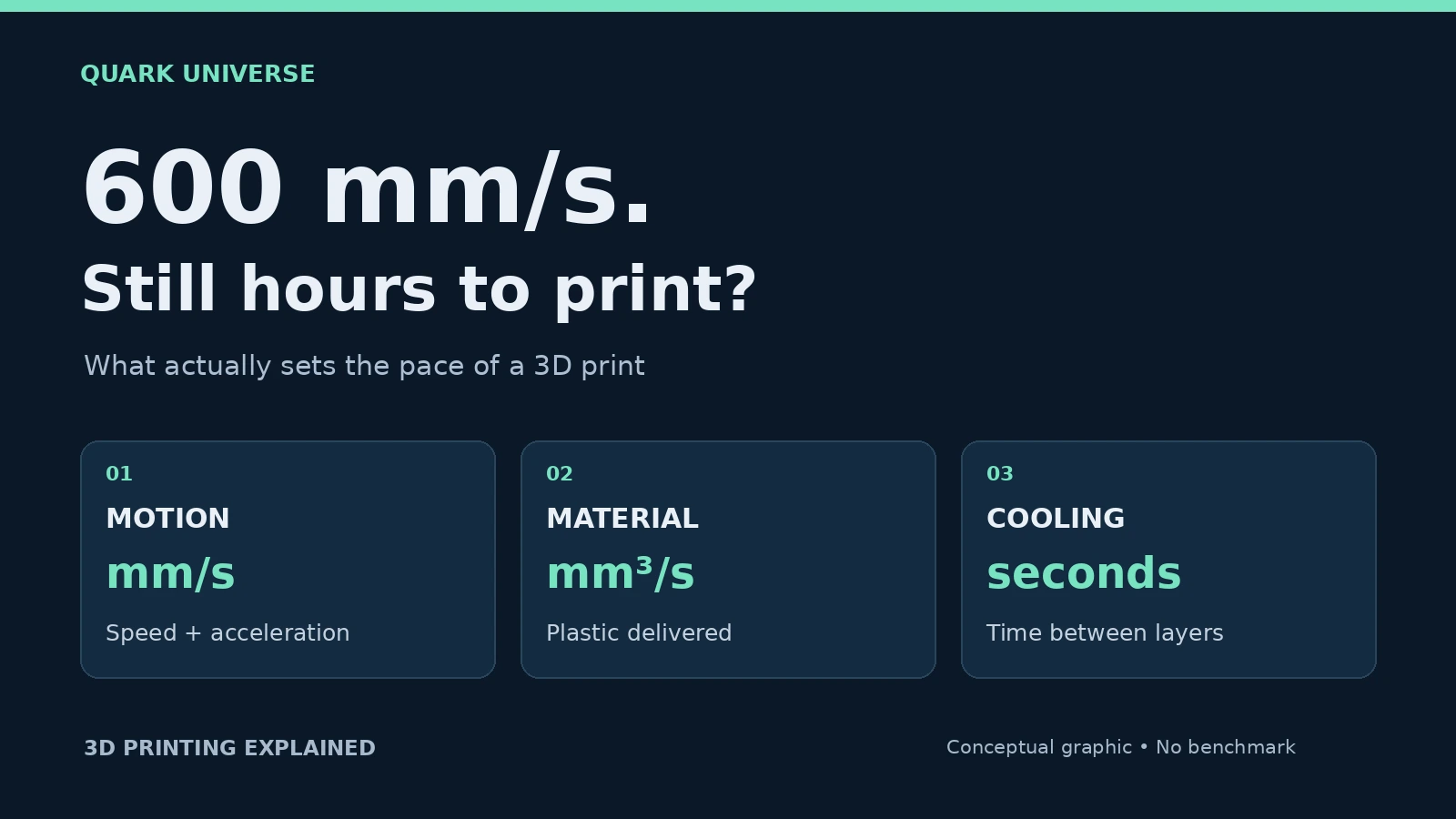
A 600 mm/s headline does not tell you how long a finished part will take. Learn how material flow, acceleration and cooling limit real printing speed, with worked examples and a practical comparison checklist.
A printer advertises 600 mm/s. You slice a small electronics enclosure, and the estimate still says three hours. Where did all that speed go?
The number on the product page is only one part of the job. To understand the estimate, you need to separate how fast the nozzle moves, how much material it deposits, and how long the part needs between layers. This guide focuses on filament-based FFF/FDM printing.
The short answer: a maximum speed is not an average production rate. A useful comparison is the time needed to make the same acceptable part, with the material and quality settings disclosed.
Check whether a specification refers to travel without extrusion, a maximum printing speed under stated conditions, or the settings used for a particular demonstration. Those are different claims.
| Quantity | Unit | What it describes |
|---|---|---|
| Movement speed | mm/s | Distance the nozzle travels per second relative to the part. |
| Acceleration | mm/s² | How quickly that movement speed can change. |
| Volumetric flow | mm³/s | Volume of plastic deposited per second. |
| Elapsed job time | Minutes or hours | Time measured between clearly defined start and finish points. |
Slicers can assign different speeds to different types of move. A high infill setting does not mean every wall or overhang uses that speed. Prusa also notes that acceleration and short moves can prevent a printer from reaching its requested speed. [2]
When comparing a demo with your own print, record the nozzle, material, layer height, wall thickness, infill and support settings. Otherwise you may be comparing two different jobs with similar-looking models.
Maximum volumetric speed limits the amount of material a profile asks the hotend to deliver. Prusa describes it as a cap that can reduce a requested movement speed when extrusion demand becomes too high. The relevant relationship is flow = extrusion cross-sectional area × movement speed. [1]
Consider an illustrative calculation using a 0.45 mm extrusion width and a 0.20 mm layer height. For an ordinary supported extrusion, a rounded-rectangle model gives an area of about 0.0814 mm². PrusaSlicer documents this type of cross-sectional model; exact handling depends on the extrusion type and slicer. [1]
| Requested speed | Calculated material demand | Compared with an assumed 20 mm³/s cap |
|---|---|---|
| 100 mm/s | 8.1 mm³/s | Below the cap |
| 200 mm/s | 16.3 mm³/s | Below the cap |
| 300 mm/s | 24.4 mm³/s | Above the cap |
| 600 mm/s | 48.8 mm³/s | Above the cap |
Calculation details: area = (width − height) × height + π × (height / 2)². With the dimensions above, area = 0.081416 mm². Multiply by each speed to obtain the table. These calculations assume nominal extrusion, without additional flow multipliers; they are not measurements.
If the profile cap is 20 mm³/s, the corresponding speed ceiling in this example is 20 ÷ 0.081416 ≈ 246 mm/s. That ceiling applies only to material delivery. It does not promise that every move reaches 246 mm/s, and 20 mm³/s is an assumed example—not a recommended setting for your printer.
This also explains why a larger extrusion is not free speed. At 0.65 mm width and 0.30 mm height, the same model gives about 0.1757 mm². The same assumed flow cap permits roughly 114 mm/s. Whether the complete job is quicker depends on how the changed toolpaths and layer count affect the whole print.
A printhead needs distance to accelerate and decelerate. Klipper documents motion planning with acceleration, cruising and deceleration phases, plus look-ahead to manage speeds between connected moves. The cruising phase can disappear on a short move. [3]
Here is a separate, idealized motion calculation. Assume a straight move starts and ends at rest, acceleration is constant at 5,000 mm/s², and the target speed is 600 mm/s. Reaching that speed takes v² ÷ (2a) = 36 mm. Slowing back to rest takes another 36 mm.
A 20 mm move under those assumptions cannot reach 600 mm/s. Its triangular speed profile peaks at √(a × distance), or approximately 316 mm/s, before it must slow down again. This calculation excludes the extrusion limit from the previous example.
Real toolpaths do not stop at every segment, and firmware may impose other constraints. The calculation illustrates the role of distance; it is not a prediction for a specific printer. Raising a top-speed field alone does not change the length of the features you are printing.
Small layers introduce another limit: the next pass may arrive before the previous one has cooled enough. PrusaSlicer can slow printing when a layer would finish below a configured time threshold, subject to its minimum print-speed setting. [4]
That makes a narrow tower a different workload from a broad enclosure. If slowdown appears only near the tip of a part, inspect cooling and layer-time settings before assuming the hotend cannot keep up.
Do not simply disable the slowdown or run every material at maximum fan speed. Prusa notes that excessive cooling can cause warping or layer separation with some materials. Keep the material requirements in view while investigating the delay. [4]
Start with a duplicate of a working profile and a saved project. Use this sequence as a diagnostic worksheet; it does not require buying an upgrade.
If material throughput is the suspected constraint, OrcaSlicer provides a maximum volumetric speed test. Its documentation emphasizes that the result depends on the machine, nozzle and filament—even brand and color can matter. It also treats the test as favorable conditions and suggests reducing the result by 10–20%, or further where necessary, before using it for normal printing. [5]
Use that test to establish a profile for the actual setup, then validate the intended part. A test that looks clean does not, by itself, establish the mechanical strength of a functional component. Do not copy an unrelated machine’s flow limit into your profile.
For a buying decision, ask for a reproducible test on a model resembling your work. A practical comparison sheet can contain:
This is our suggested comparison method, not a formal benchmark standard. Equal settings help isolate performance differences; equal finished-part requirements help answer which machine suits the job. Be clear about which comparison you are making.
For a workshop printing electronics cases, one useful result might be the time required to produce a case whose lid fits, mounting holes line up, and visible surfaces need no rework. A fast demonstration of an unrelated shape cannot answer that question on its own.
Open one model you genuinely plan to print. Check its speed and flow previews, identify where the time goes, and save a baseline before changing anything. If you are shopping, ask for the same kind of evidence from a reviewer or supplier. That will tell you more about usable speed than the largest mm/s number on the box.
This is a documentation-based explainer, not a hands-on printer review. Numerical examples are original calculations under the stated assumptions. The 600 mm/s figure is a hypothetical headline specification and is not a claim about a named product. Sources checked on 21 October 2026.
